
Designing and fabricating a split flap display for a group project where we made an automata of an auditorium
Skills: CAD, (CNC) Mill, Lathe, Laser Cutter, Waterjet, Plasma Cutter

The first team project in Mechanical Prototyping was to create a visually interesting kinetic sculpture driven by a DC motor. In addition to size constraints, the main requirement was to use a variety of mechanisms and manufacturing techniques. As the theme for the project was "Only at Olin" our group chose to create an automata depicting the relationship Oliners have with our one and only auditorium/lecture hall, known as "The Nord."

My primary responsibility on the team was the design and manufacture of the split flap display, which represents the projector screen in the auditorium. I designed it to be mostly aluminum with quickboard flaps, acrylic side panels, and COTS pulley hardware.

I created an initial prototype out of MDF and cardstock to verify that the general idea would work. I was originally planning to use a geneva wheel to reduce the revolution rate and make the slides incremental, although this prototype taught me that the split flap would flop around when not engaged with the driven geneva wheel, so I decided to simply use a larger pulley to reduce the input RPM. This prototype also featured bearings on the flaps which proved unnecessary and were removed in the final design, allowing the number of flaps to be increased from 6 to 10 in a smaller footprint.

The basic geometry of the side support pieces was cut out on the waterjet. Important mating faces were then milled flat and the mounting holes were drilled and tapped on the mill.


The wheels that hold the flaps were milled using the 2.5 axis conversational on the mill. Stock was cut to rough size on the bandsaw and then the hole pattern was drilled and reamed to size. This part was then bolted to a fixture plate that was machined earlier which allowed for the circular profile to be cut. A pin in one of the holes prevented the part from rotating.


These parts were then press fit onto a stainless steel shaft that I cut using a horizontal bandsaw and lathe.

The top bar was machined on the lathe. It has tapped ends and is held in a slot on the side brackets, which allows for adjustability of the timing of the flipping of the flaps.


The bar was then installed between the slots, giving the display some structure.

At this point all of the metal fabrication for the display was completed and it was time to focus on the flaps themselves.

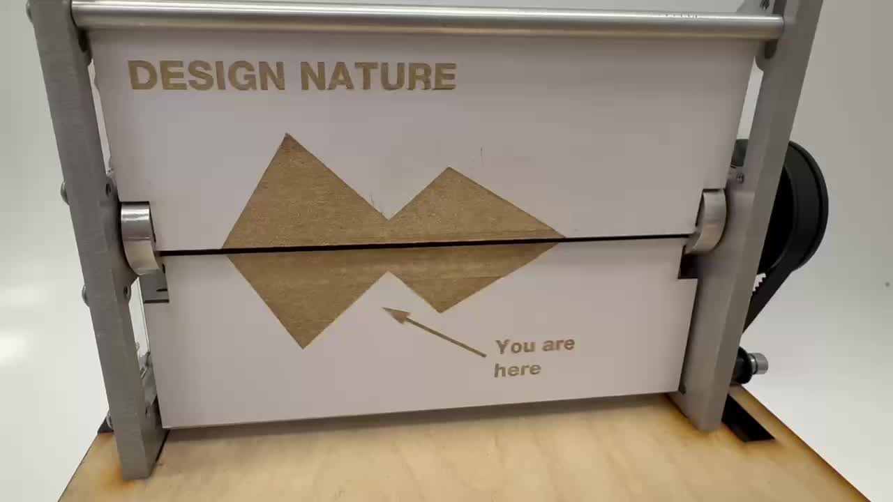
The flaps were laser cut out of white quickboard. This was a convenient material as it allowed for multiple inexpensive iterations and was also flexible. This flexibility allowed flaps to be installed and replaced without moving the metal wheels out of place by simply bending the panel to fit it into place. The flaps were cut out of a sheet of material which was taped in place, allowing for the individual flaps to be flipped over and rastered on both sides. A number of Olin classes were depicted on the slides.

The final step in the structure of the split flap was adding the acrylic side panels. While not exactly true to the real projector screen, these cutouts allow for viewers to see the interesting motion of the split flap better than a solid wall would allow.
The split flap was attached to the main laser cut box structure through the use of finger joints/tabs with machine screws retaining the aluminum brackets in place.

While the main drive of the box was powered by a chain, the split flap integrated with the powertrain through the usage of a belt. This was connected to a small pulley on the driven shaft with the larger pulley on the axle connected to the display, resulting in the reduction in speed that I desired. The split flap is at right in the image below

I am extremely pleased with my final split flap design. It functions well and looks appealing, at least in my opinion. I encountered a number of challenges in the process of making this project and gained more machining experience. The first challenge that I encountered during this project was that even with an accurate CAD model, it was difficult to fully understand how the flaps would move, as the model lacked gravity. To solve this problem, I created a physical prototype which helped me gain a better intuition. I also designed the positioning of the upper and lower flap stops to use slots, which allows for adjustability to make the optimal angle for both halves of the display. The second challenge that I ran into was adding graphics to both sides of the flaps. I knew I didn't want to print out images and glue them on, so I decided to laser cut the graphics along with the outer shapes themselves. I achieved a double sided effect by taping the sheet of material in place on the bed of the laser cutter such that after the first side was cut and rastered I could flip the flaps over in their places without adjusting their locations and messing up the zeros. A final challenge that I had while assembling was press-fitting the machined aluminum wheels onto the stainless steel shaft with a specific distance between them, while also aligning them. I solved this problem by threading 1/8'' welding rod through the holes on the wheels during the process to ensure alignment. I then created a stack of scrap material of the correct distance that I wedged between the wheels while pressing the second into place. I've very satisfied with the result and it works quite well.
